Vhdl Code For Serial Adder Using Finite State Machine
- Vhdl Code For Serial Adder Using Finite State Machine
- Vhdl Code For Serial Adder Using Finite State Machine Designer
- Vhdl Code For Serial Adder Using Finite State Machine Diagram
- Vhdl Code For Serial Adder Using Finite State Machine Calculator
- 4 Bit Serial Adder
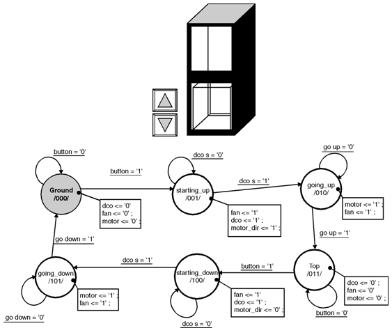
Finite state machine is a graphical model/representation of sequential activities or events. After representing and modeling the events they can be implemented easily in case of sequential logic designs. Finite state machines can be utilized in many fields of study e.g neural networks, artificial intelligence, mathematics, games, robotics and sequential flow of data. Since we are dealing with the sequential circuits so i will explain their use in sequential circuit design in this tutorial. |

- Melay Machine
- Moore Machine
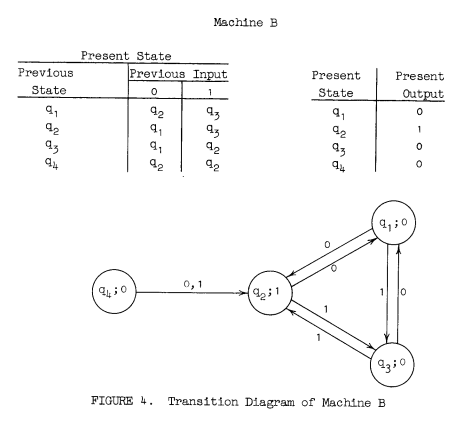
Register the block diagram is attached, vhdl code for serial adder using moore type fsm serial adder verilog 4 bit serial adder when doing digital system design it is very common to begin by defining how the system works with a finite state machine model this design step allows the designer to think. Keywords— D-latch, Finite state machine, Mealy Model, Multisim, Serial adder. INTRODUCTION TO FINITE STATE MACHINE Based on the state table we can construct the state diagram. The state diagram is as shown in Fig 2. As observed in the state A finite state machine can be represented by a state transition table or a state diagram.
Moore Machine
- More number of states in moore compared to melay for same fsm.
- States changes after 1 clock cycle. Latency = 1.
- Synchronous output. Because the states are determined in a process.
- States are output.
Mealy Machine
- Less number of states in mealy compared to moore for same fsm.
- State transition on the same clock cycle. Latency = 0.
- Asynchronous output.
- Transition are output.
Vhdl Code For Serial Adder Using Finite State Machine

A state machine is a sequential circuit that advances through a number of states. To describe a state machine in Quartus II VHDL, you can declare an enumeration type for the states, and use a Process Statement for the state register and the next-state logic.
Vhdl Code For Serial Adder Using Finite State Machine Designer
The VHDL example shown below implements a 3-state state machine.

This state machine includes a Process Statement that is activated on every positive edge of the clk control signal for the next-state logic, and a Process Statement that is activated on a change in the state variable. This state machine has an asynchronous reset, which the Compiler recognizes.
Vhdl Code For Serial Adder Using Finite State Machine Diagram
Note: The Compiler also recognizes state machines with a synchronous reset. |
The signal state stores the current state of the state machine. The declaration of the type STATE_TYPE defines the states s0, s1, and s2 for state_machine.
At startup, the state machine is initialized to the reset state. If there is no reset state, the state machine is initialized to the first state in the Type Declaration. Otherwise, the first Case Statement determines the transitions between the states (that is, which state to enter on the next rising edge of clk) and the second Case Statement determines the value of the outputs for each state.
Vhdl Code For Serial Adder Using Finite State Machine Calculator
The Compiler recognizes state machines and reports them as such in the State Machines section of the Report window only if all of the following conditions are met:
The type of the signal or variable that represents the state machine must be an enumerated type.
The Process Statement that describes the state machine must be clocked, and must contain an If Statement that checks for a positive edge of the
clkcontrol signal.The state machine behavior, that is, the next-state logic, is defined with Case Statements at the top level.
All assignments to the signal or variable that represents the state machine are within the process.
The state machine must have more than two states. Instant immersion english software, free download.
VHDL state machines that do not meet these conditions are converted into logic gates and registers that are not listed as state machines in the Report window. The Compiler also converts VHDL state machines to 'regular' logic when the ENUM_ENCODING attribute is used to manually specify state assignments in a project.
Note: Because the Compiler usually produces the best results, Altera recommends that you do not use the |
4 Bit Serial Adder
You can assign states in the following ways:
For more information, refer to the following sections of the IEEE Std 1076-1993 IEEE Standard VHDL Language Reference Manual:
Section 8.1: Wait Statement
Section 8.6: If Statement
Section 8.7: Case Statement
Section 9.2: Process Statement